DC Filament Supply Test
ClariSonus Research Report #002
by John Atwood
March 14, 2007
(updated March 23, 2007)
This report is licensed by the Creative
Commons Attribution-NoDerivs 2.5 license.
Introduction
After discussions with Lynn Olson on the merits of different designs
for filament supplies, I decided to compare various design topologies
and take some measurements. These measurements and waveforms are
referenced in Lynn's posting on the ClariSonus blog.
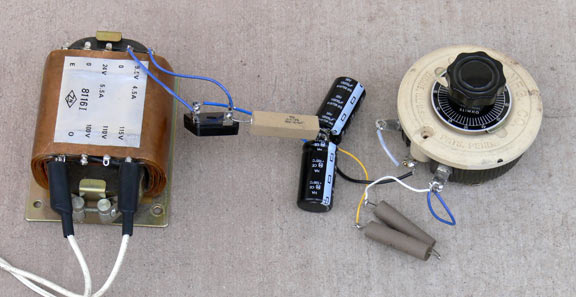
A representative filament load was chosen: 5.0V at 2.5A.
This is roughly equivalent to two 300Bs in parallel or one
"super" 300B. To avoid blowing out tubes, a 2.0 ohm 20W power
resistor was substituted as the load. A large C-core transformer
with a "9.5V" at 4.5A winding was chosen. The primary is rated at
115V. It has another 24V, 5.5A winding that was unused.
When powered from a 120V line, the output is about 10V. The
filter capacitors are Panasonic type ECO-S1VA103CA 105°C types.
The bridge rectifier is an old (1970) Motorola epoxy-encased 12A,
50V type. The capacitor charging current is measured by a 4-wire
power resistor with an experimentally-determined resistance of 6
milliohms. Since this circuit exists only for this report, no
effort was made to put it on a chassis, so it is "air-insulated" as
this picture of circuit #1 shows:
Various topologies were tried that, where possible, used the same
components. A problem is that these different topologies
give different output voltages. In order to simulate the same
tube filament load, either the input voltage could be changed, say by a
Variac, or the voltage could be dropped by a power resistor right
before the load. Since I didn't want to insert any extra
impedances between the power line and rectifier, the latter was chosen.
A large 7.5 ohm rheostat was used to drop the voltage to 5.0V.
The resistance setting of the rheostat is listed in each
schematic.
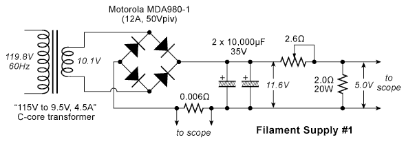
Circuit #1 - Simple Cap-Input
Circuit number one is a simple capacitor-input supply seen in
nearly every DC filament supply, as well as virtually all solid-state
amplifiers. It has the merit of simplicity, but several
disadvantages electrically. Here is the circuit:
One of the biggest problem with this topology is that current is drawn
from the line in short bursts at the top of each cycle. The
larger the capacitors and the lower the impedance between the power
line and the capacitor, the bigger the charging pulses. These
pulses have high harmonic content, and if there is any open loop area
where this current flows, a magnetic field is generated which will
inject this noisy signal into signal loops. Also, if the signal
ground is carelessly connected to the wrong place, such as right at the
rectifier terminal, then voltage drops in the wiring will inject these
pulses into the ground system. The sound of both of these
problems is a characteristic "buzz" at twice the line frequency.
Another problem is that the ripple voltage is not sinusoidal, but
rather somewhat like a sawtooth wave, again with high harmonic content.
Here are the waveforms and peak-to-peak values of the charging
current and output ripple:
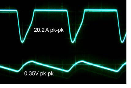
The width and amplitude of the charging pulse are, frankly, less
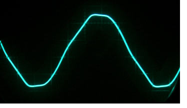
than I would have expected. On further examination, I found that
the waveform at my house was pretty lousy, with flat-tops that would
extend the charging times. Here is the waveform, as measured at a
wall-socket in a circuit with no other loads, so is representative of
what is present on my main circuit-breaker panel:
Circuit #2 - Cap-Input with Resistance Ahead of Capacitor
Instead of dropping more than half the DC voltage in the rheostat,
what about putting the resistance ahead of the capacitors? The
rheostat was moved over and readjusted to give 5.0V output:
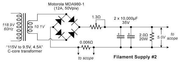
Note that the rheostat is now at about half the previous value.
This is because voltage is only dropped during the narrow, but
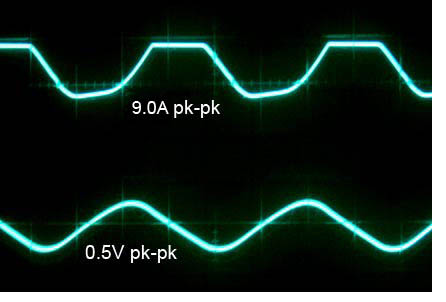
large charging pulses, so less resistance is needed. The charging
pulses are less than half as big and are spread out to about 2/3rds of
a cycle (a cycle here being 1/120th of a second). The
ripple voltage is a little higher, but now nearly sinusoidal:
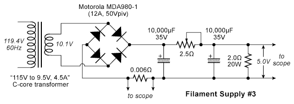
Circuit #3 - Resistance Between Two Capacitors
What happens when we use a two-stage filter, in other words a
cap-input charging capacitor follower by an R-C filter section?
By putting the rheostat between the two 10,000µF
capacitors, this can be done without increasing the amount of parts in
the circuit. As expected, the rheostat value is close to the
value in circuit #1, since it is dropping mostly DC voltage. Here
is the circuit:
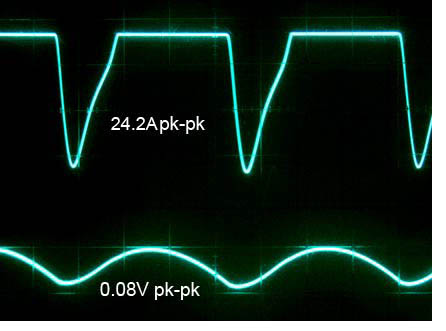
This circuit configuration produced two surprises: the good one
is that the ripple is very low, but the bad one is that the charging
current is higher than in circuit #1. The low ripple shows the
benefit of having an actual filter capacitor in the circuit. (Note that
I have been not been calling the input capacitor a "filter" capacitor,
but rather a "charging" capacitor, which is really its actual function.
This is case where semantics affect people's understanding of the
physical world - by calling the first capacitor a "filter" capacitor,
they think that by making it bigger, it will filter better. It
often doesn't.) I'm not sure why the charging pulses are higher
- they should be lower, due to the lower input charging
capacitor. Maybe the R-C network following it sets it up to
charge faster. SPICE simulation might help here.
Circuit #4 - Choke Input
In the final circuit, one of the 10,000µF capacitors is
replaced by a choke. This is not a cost-constant trade, since the
choke is much larger, heavier, and more expensive than the capacitor.
Here is a size comparison:
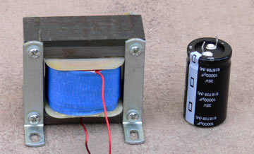
The choke is a hand-wound prototype used for the Artemis Labs SP-1
amplifier, where it is used in a choke input supply for a "super" 300B
filament.
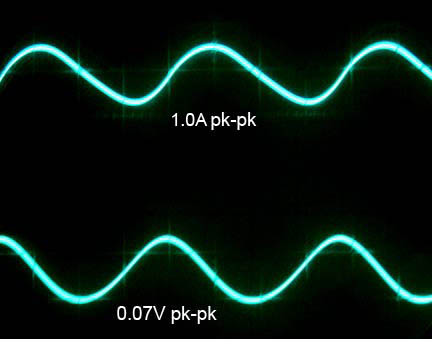
This time, there was little excess voltage from the supply, so the rheostat was almost at zero ohms:
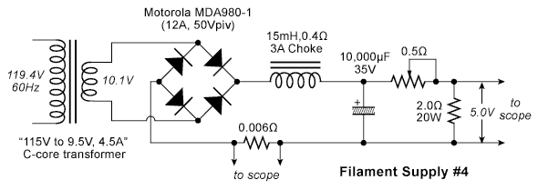
Several notable things here: the ripple is very low and almost
sinusoidal, and the "charging" current is very low - a 1.0A near sine
wave. At first I was a little confused, because this AC current I
measured was significantly less than the AC current drawn from the
transformer. Then I realized that this is the "ripple" current.
If I moved the 0.006 ohm sense resistor to the AC side of the
bridge, I would see the actual line current waveform. The larger
the choke inductance, the lower this ripple current will be, and also
the lower the output voltage ripple.
Ripple and Charging Spectrum
To show the difference between the topologies in frequency spectrum,
circuits #1 and #4 were analyzed by my Audio Precision System 2.
All the following plots are just showing relative dB levels, but
the settings were not changed when the circuits were changed, so that
the comparisons were "apples-to-apples".
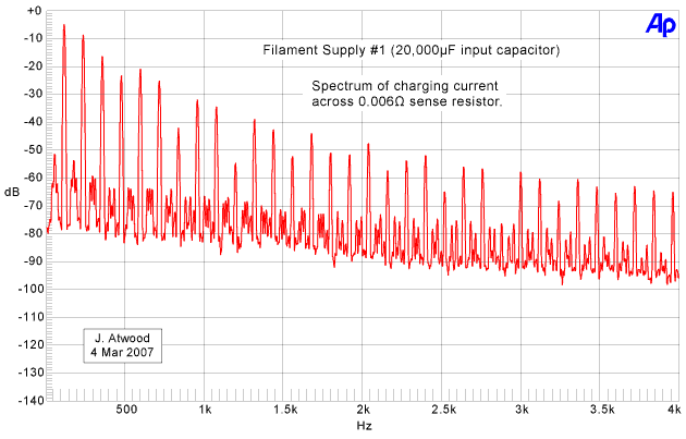
First, let's look at circuit #1. As expected, both the
charging current and ripple voltage have significant high-order
harmonics. One minor note: if the line current rather than
charging current would have been measured, the even-order terms would
have been a bit larger.
The harmonics on the charging current are only about -55dB down at 3KHz, compared to the 120Hz fundamental:
For the ripple voltage, the harmonics are about -65dB down at 3KHz:

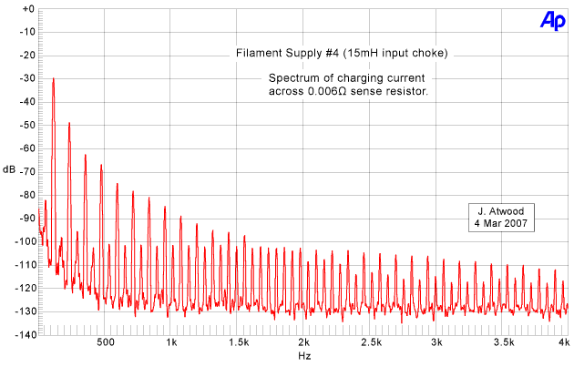
Now, let's look at the choke input circuit #4. First of
all, the 120Hz charging current fundamental is -25dB below the
cap-input case, and the high-order harmonics fall off a lot faster.
At 3KHz, the harmonics are -75dB down from the 120Hz fundamental:
For the ripple voltage, the drop-off is even faster:

Even the "noise floor" between the 60 and 120Hz harmonics is lower in
the choke input case. Circuit #3 would have a charging current
spectrum similar to circuit #1, but a ripple voltage spectrum just
slightly worse than circuit #4.
Update (23 March 2007): A
ClariSonus reader requested more FFT plots, especially of circuit #3.
I re-constituted the circuit and took FFT plots using the same
settings as above. Here are the plots of current and ripple
voltage for circuit #3:
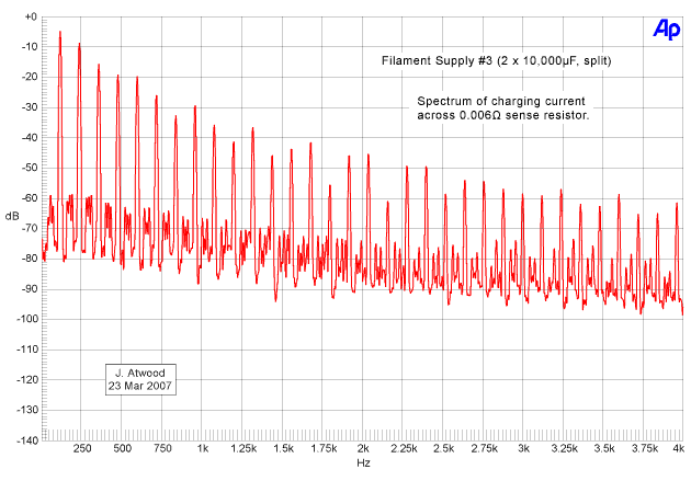

As predicted above, the charging current is similar to circuit #1 and
the voltage ripple is similar to circuit #4. However, close
comparison shows the following differences:
- The low-order current harmonics are almost the same.
- The high-order current harmonics are very slightly higher.
- The ripple voltage harmonics and noise floor are 10 to 20dB
higher than in circuit #4, but 15 to 25dB better than circuit #1.
At the request of a reader, Schottky rectifiers were tried in place of
the conventional silicon bridge rectifier. The rectifiers used
were General Semiconductor brand MBR-1045 rectifiers rated at 10A
and 45V. They are in a two-lead TO-220 package and four were
wired in a bridge. They were substituted into circuit #3 and
identical FFT plots were made as above. Here are the current and
ripple voltage waveforms:
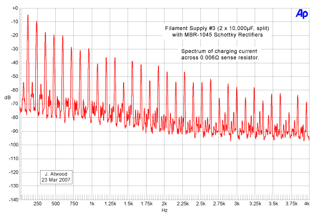

The lower voltage of the Schottky rectifiers resulted in a 0.3 volt
increase in output voltage. To compensate, the rheostat was
increased to 2.8 ohms to keep the output at 5.0 volts. The
results were quite similar, but on close inspection the following can
be noticed:
- The charging current is virtually identical, except above the 22nd harmonic, where it is lower.
- The ripple voltage low order harmonics (1st to 3rd) are about 2 to 4 dB lower.
- The ripple voltage medium order harmonics are just slightly higher.
- Very high order voltage harmonics (over the 22nd) are noticeably lower.
The reduction in ripple voltage may be caused, in part, by the slightly
higher rheostat setting. The main difference seems to be above
2.5KHz, where the harmonics are less with the Schottky rectifiers.
The advantage of high speed rectifiers, such as Schottkys, is
mainly apparent at high frequencies, where the reduction of glitches
caused by stored charge are reduced. This test isn't really set
up to measure this, although it becomes noticeable above 2.5KHz.
Another set of tests needs to be run focusing on the higher audio
frequencies up into the RF domain to compare rectifiers.
Conclusion
The ubiquitous capacitor-input filter is really quite noisy, and almost
always requires additional filtering or regulation to eliminate ripple.
However, the noisy current draw pollutes everything upstream from
the rectifier, and can easily get into other circuits. Adding
series resistance helps reduce the charging current, but doesn't help
the voltage ripple. Even just a little bit of RC filtering
drastically reduces the ripple. A choke-input supply makes both
the current and voltage ripple very small. In addition, its quick
drop-off of harmonics means that any leakage into signal circuits is
not as noticeable, since, due to the Fletcher-Munson curve, the ear is
less sensitive to low-frequency noise. If the lack of voltage
regulation with load current can be tolerated then circuits #3 and #4
could drive DHT filaments directly. Circuits #1 or #2 would
require additional filtering to keep the audible noise down.